Floor Plan 101: Your Guide to Symbols, Scale & Space
Whether you’re buying a home, working with an architect, or starting your own design project, understanding a floor plan is essential. A well-drawn plan is like a language; once you learn to read it, you can visualize the entire space on paper.
In this guide, we’ll break down floor plans step by step: what they are, the symbols that are used, how to read dimensions, how to interpret wall types and doors/windows, and dive into details so you’ll never feel lost staring at a drawing again.
1. What Is a Floor Plan?
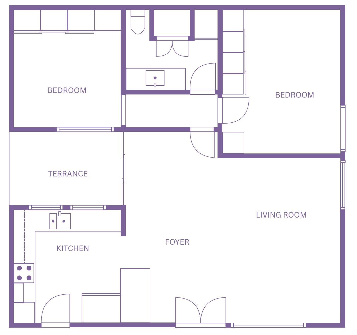
A floor plan is a scaled drawing that shows the layout of rooms, walls, doors, windows, stairs, and fixed installations (like kitchen counters or bathroom fixtures) from a top-down view, as if the roof were cut off at around 4 feet above the floor.
It’s one of the most fundamental drawings in architecture and interior design, often paired with elevations and sections.
2. Understanding Scale
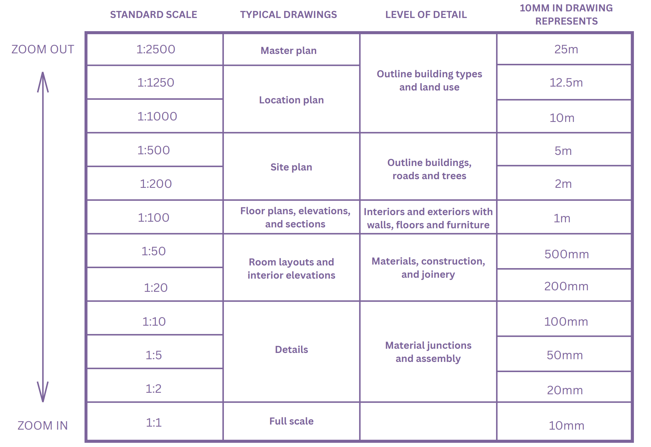
Scale tells you how the drawing relates to real-life dimensions. Common architectural scales include:
1" = 1'-0": A full-scale representation, useful for life-size details or mockups.
1/4" = 1'-0": Commonly used for residential floor plans, representing a 1:48 scale.
1/8" = 1'-0": Used for larger structures or commercial plans, representing a 1:96 scale.
1:100: A general-purpose scale for larger buildings, site plans, and elevations.
Always check the scale bar or title block it’s usually at the bottom of the drawing. If in doubt, use a scale ruler to measure.
3. Wall Types & Line Weights
Walls are drawn using different line weights to distinguish between structural and interior partitions:
Thick solid lines = exterior/structural walls
Thinner solid lines = interior partitions
Dashed or dotted lines = elements above the cut plane (overhead cabinets, beams)
Double lines = walls with thickness (masonry)
Single line = partitions like glass walls or thin dividers in schematic plans
4. Doors, Windows & Openings
Doors
Many people don’t realize that door and window sizes on plans are written in a shorthand that represents feet and inches. For example, a door labeled “3068” means it’s 3 feet 0 inches wide and 6 feet 8 inches tall.
Windows follow a similar format and often include letter codes like “DH” for double-hung or “SC” for single casement to indicate the window type.
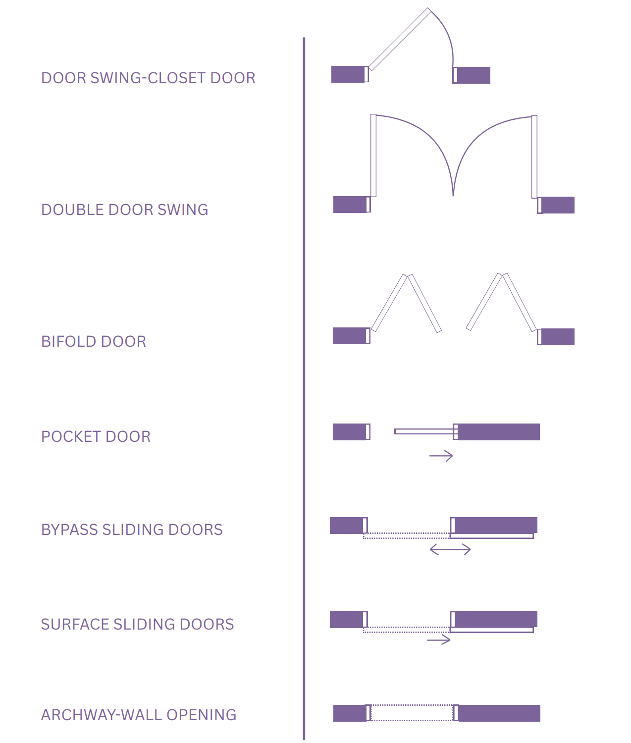
Beyond sizing, door symbols on drawings also communicate how each door operates. In floor plans, doors are represented by simple linework and arcs that show the swing direction. For example, closet doors, double doors, bifold doors, pocket doors, and sliding doors each have their own distinct symbols, making it easy to understand how the openings function within the space:
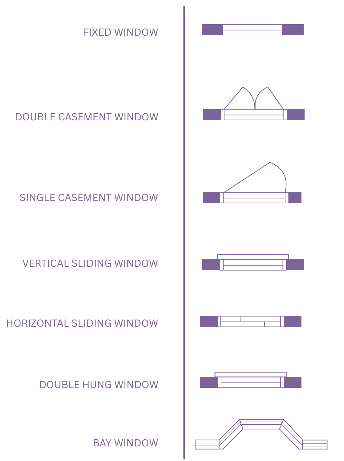
Windows
Windows are typically drawn as breaks in walls with parallel lines or thin rectangles indicating the glass panel. They can also be symbolized with short lines perpendicular to the wall.
Openings
Openings without doors (archways) are shown as gaps in the wall with no arc.
5. Dimensions: How to Read Measurements
Floor plan dimensions are usually drawn outside the floor plan, in lines parallel to the walls. There are typically three-dimensional strings:
Overall building dimensions (outermost)
Centerline or structural dimensions (middle)
Room-by-room or opening dimensions (innermost)
Key things to remember:
Dimensions are measured from finish to finish or centerline to centerline, depending on the drawing standard.
Numbers are given in feet-inches (U.S.) or meters-millimeters (most of the world).
Symbols like ' = feet and " = inches.
6. Furniture & Fixtures Symbols
Floor plans often include furniture layouts to show the intended use of space. These are drawn with lighter lines or simplified outlines:
Rectangles with lines for tables.
Toilets, sinks, and bathtubs have standard schematic symbols (often consistent across drawings).
7. Orientation & Reference Information
Look for:
North Arrow: Shows orientation (important for sunlight analysis).
Title Block: Typically includes project name, date, scale, drawing number, and author.
Room Names & Numbers: Indicate intended use (Living Room, Bedroom).
Section Marks: Small circles with arrows and letters (A-A) showing where sections are cut.
Elevation Marks: Similar, but reference vertical drawings.
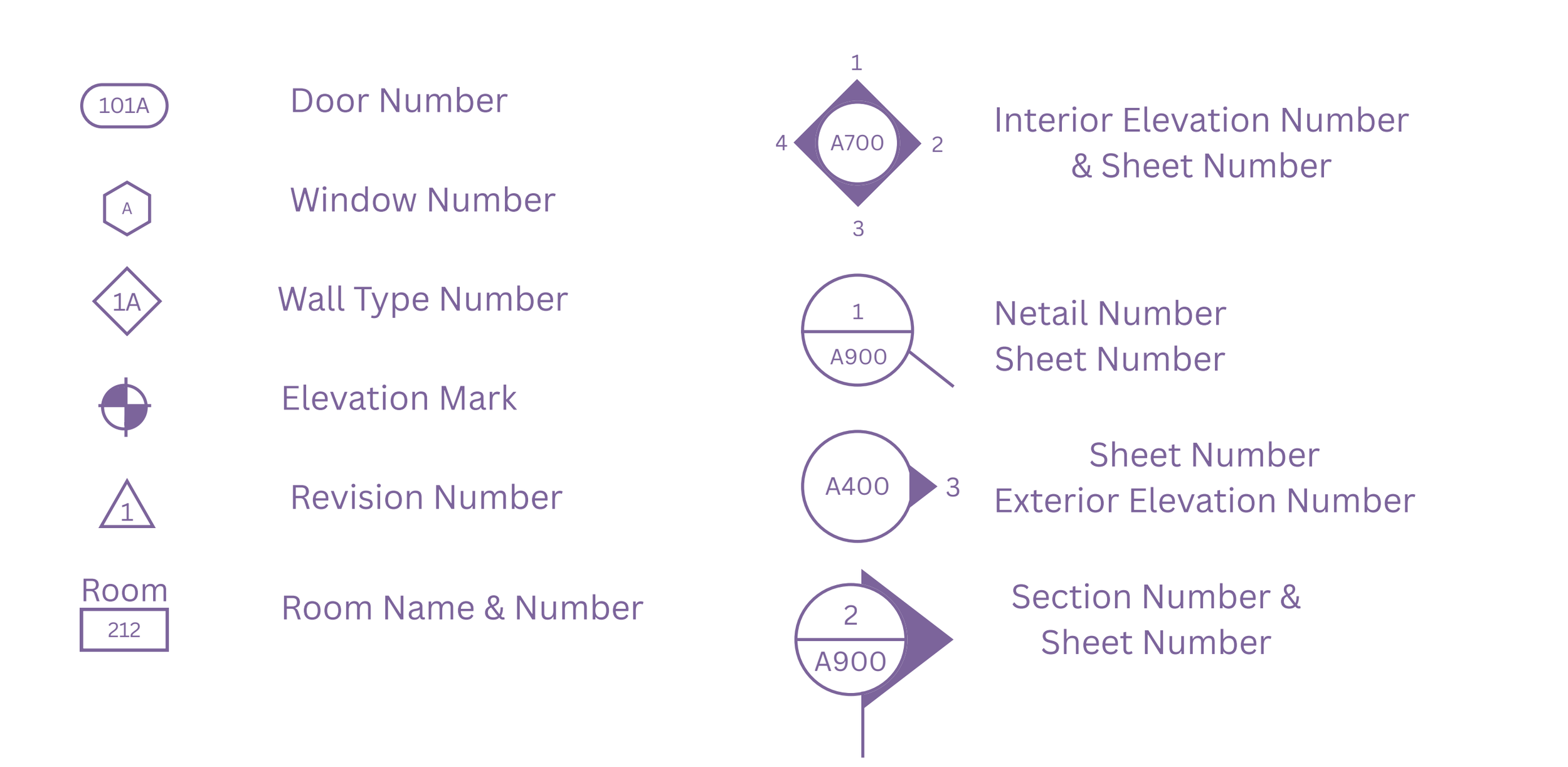
8. Common Symbols & Legends
Most floor plans include a legend, a small box that explains all symbols that are being used in the plan.
Typical symbols:
9. Special Elements
Depending on the project, you might also see:
Level markers: Small annotations indicating floor height relative to a baseline.
Hatching/patterns: Different materials (tile, wood, concrete, grass) shown with unique hatch patterns.
Ceiling elements: Shown dashed (soffits, beams, skylights).
Stairs: Indicated with a series of rectangles and an arrow showing “up” or “down” direction.
Final Tips
Always check the scale and north arrow first.
Don’t ignore dashed lines; they often indicate something overhead that could affect design.
If something’s unclear, refer to the legend or title block.
When designing, use consistent symbols and hatching so others can read your drawings easily.
Understanding a floor plan gives you the power to visualize spaces clearly, communicate ideas effectively, and make informed decisions about your home or project. But reading a plan is just the beginning; bringing it to life takes expertise, creativity, and precision. At Jane Draws Plans, we help turn lines on paper into spaces you’ll love living in. Whether you’re renovating, building, or dreaming up something new, get in touch to start shaping your vision together.